- Background
- Reverse Engineering
- ESP32 Controller
- Code
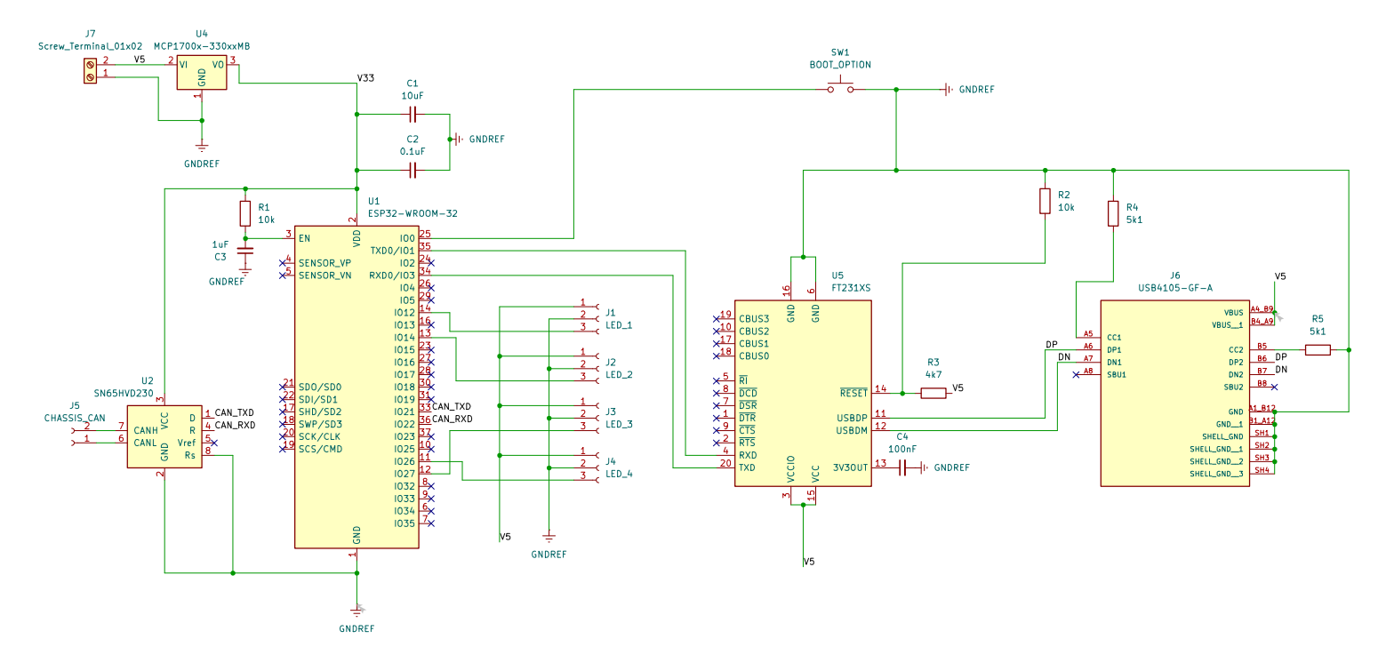
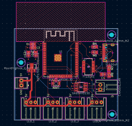
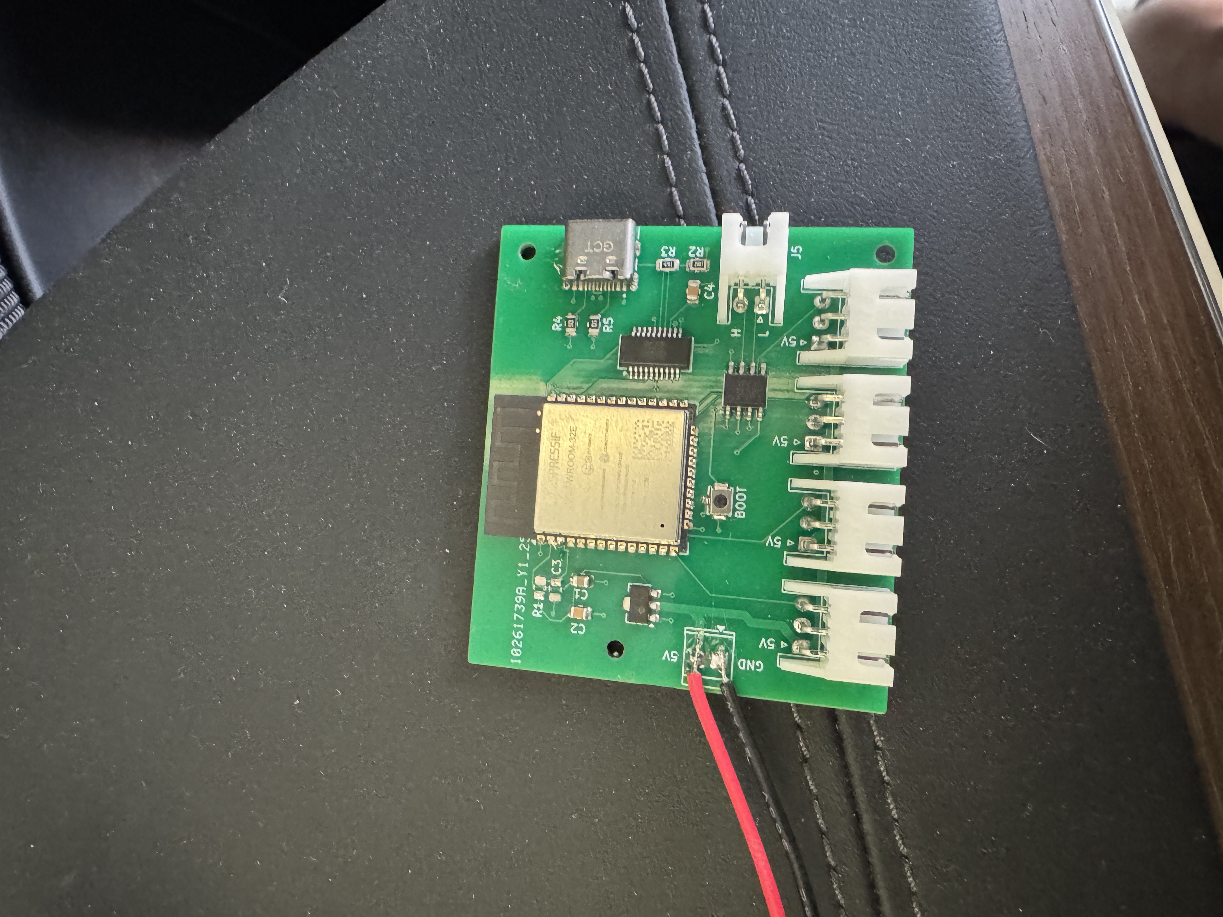
- Schematic and Custom PCB
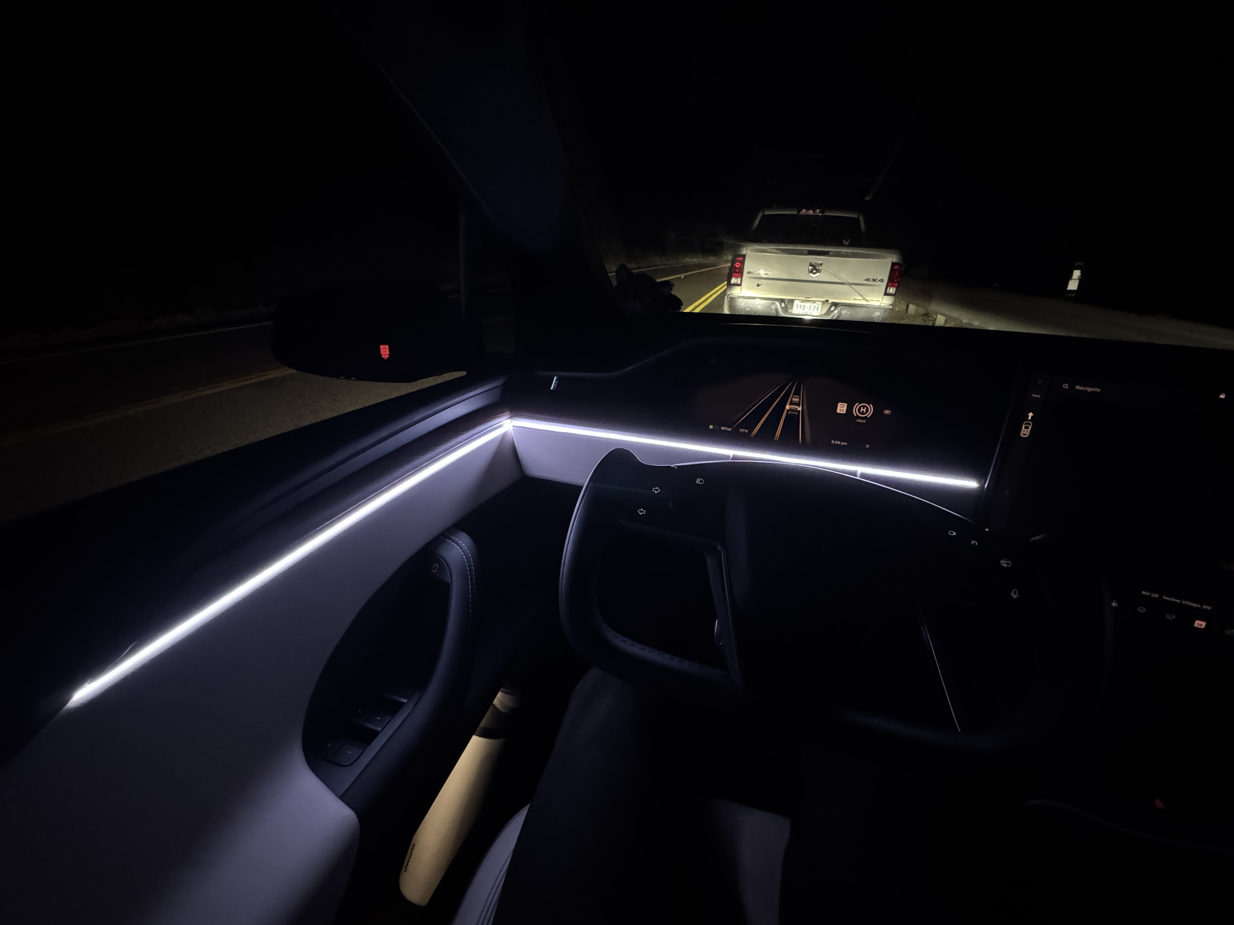
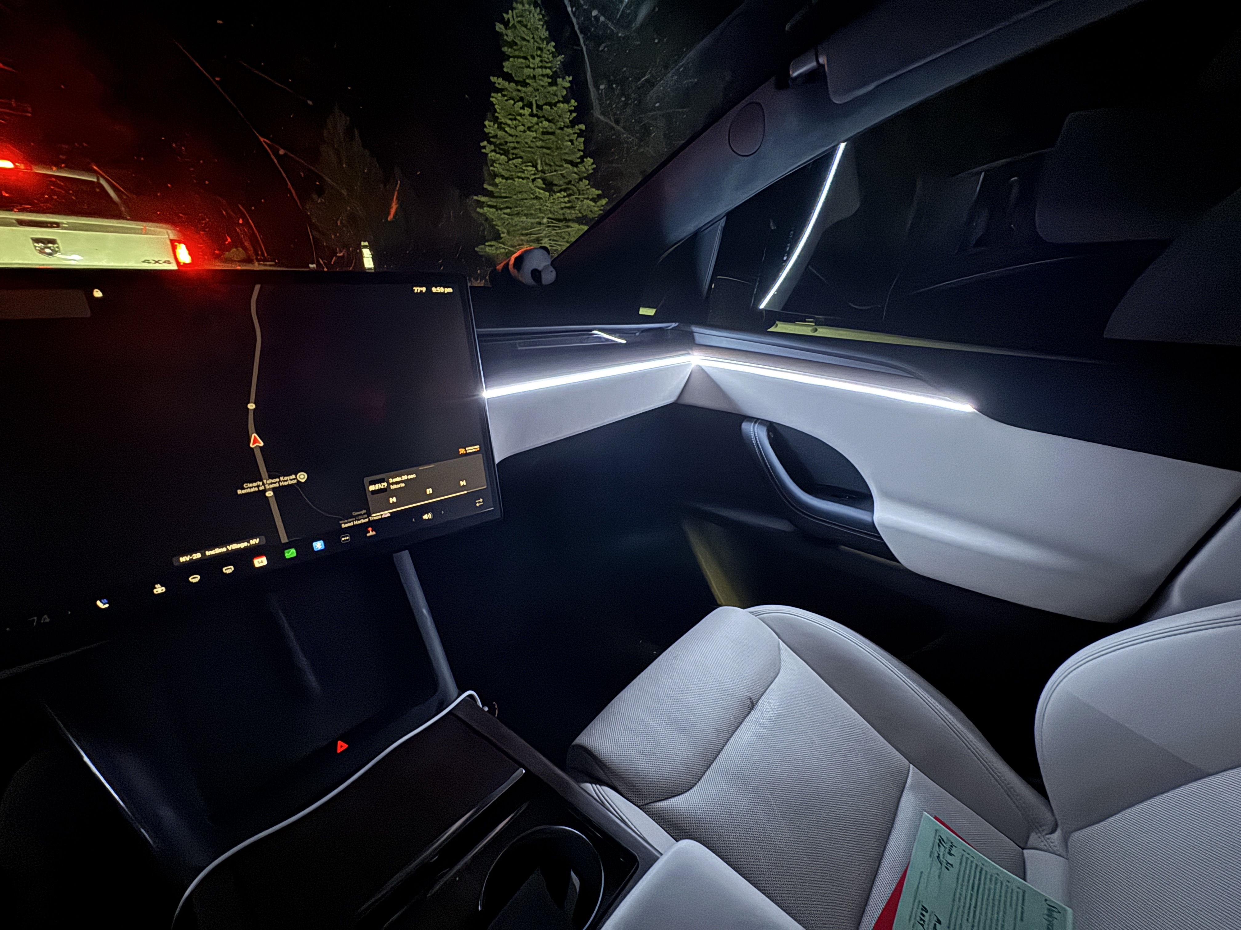
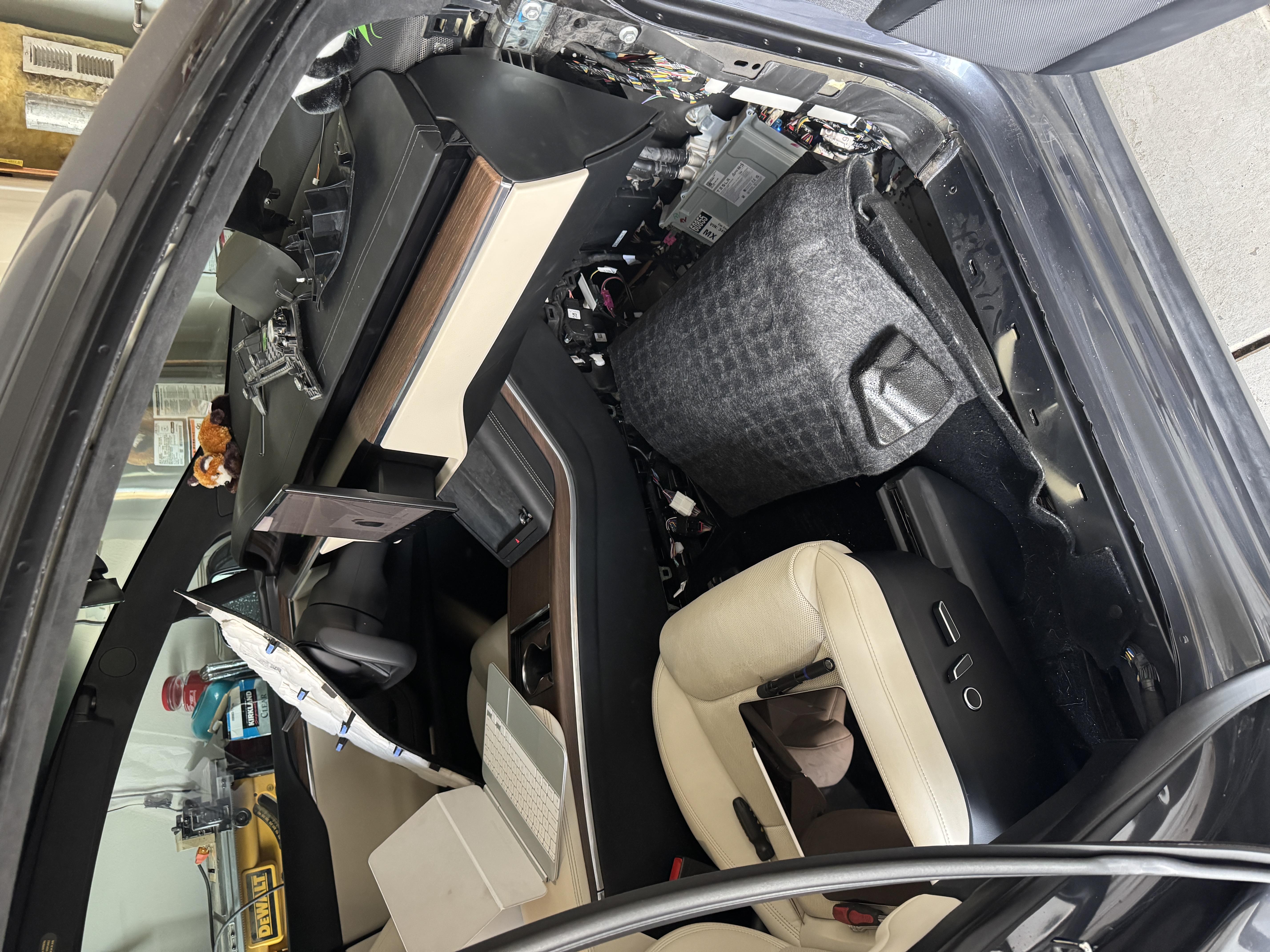
- Installation
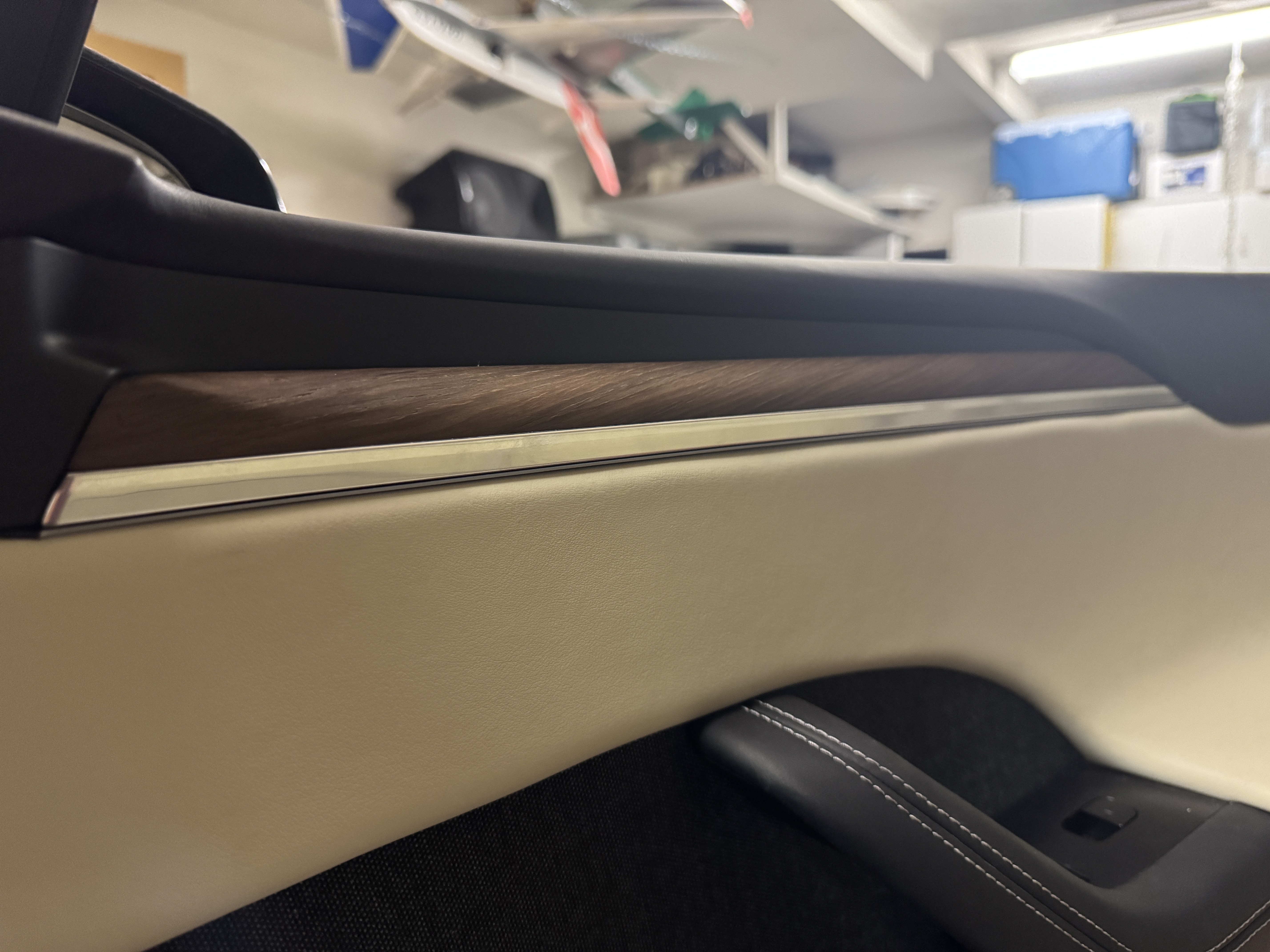
- Finished Product
I also blew up another LED strip when I inadvertently turned on my bench
top power supply when it was set to 10V and still connected to the breadboard.
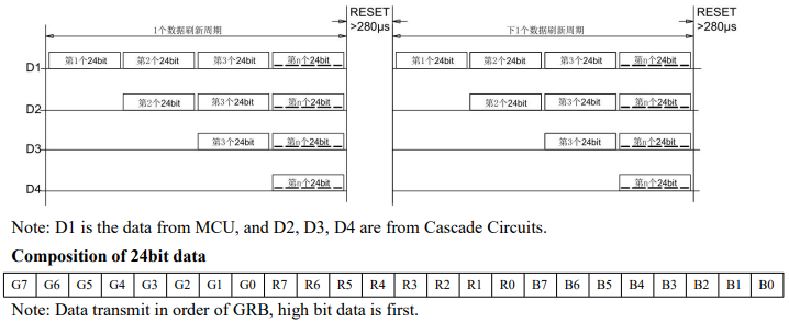
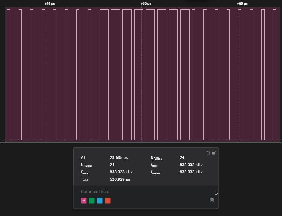
- An array of 24-bit packets are sent to the strip by the controller
- Packet contains 3 bytes, one for each color, in GRB order
- The individual bit values are distinguished by the time the data line spends HIGH and LOW (refer to the WS2815 datasheet specific timing numbers)
- Each individual LED reads the first packet in line, and shows the corresponding RGB value
- The remaining packets are passed along to the next LED in line
- Process repeats until packets run out or until the last LED in line
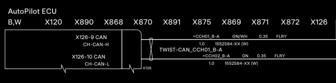
- As a side note, the Model X can bus uses a 500kbps bit rate
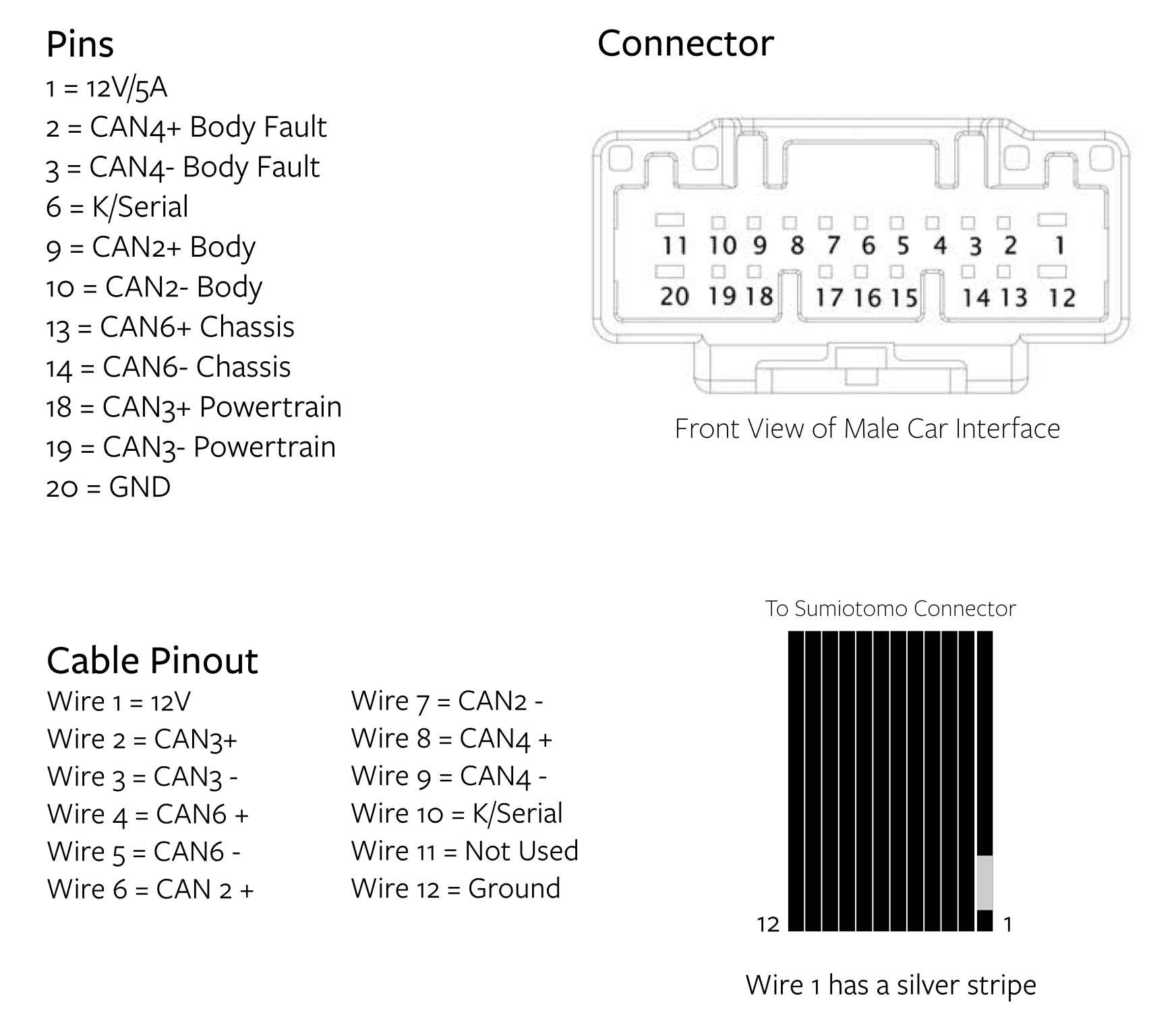
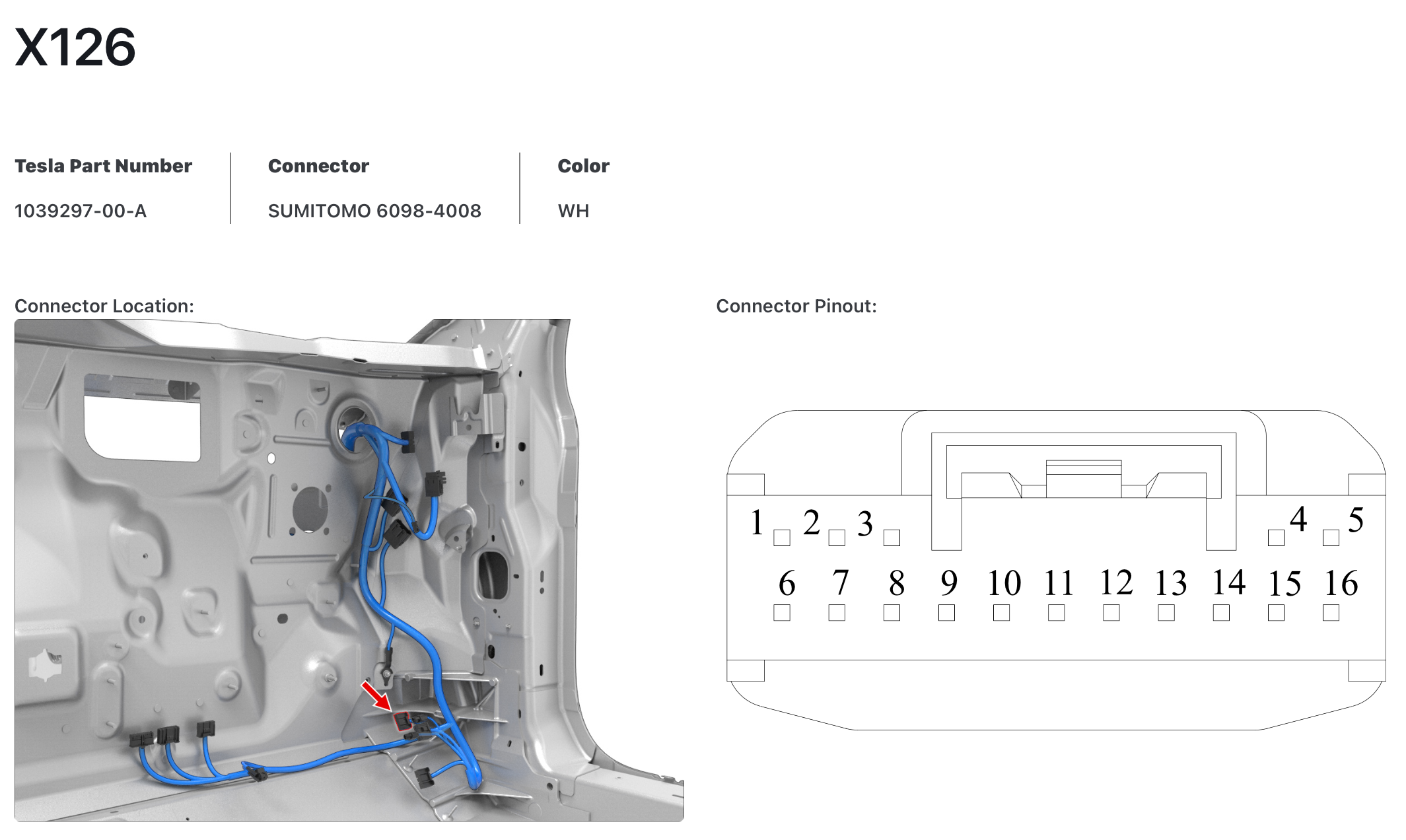
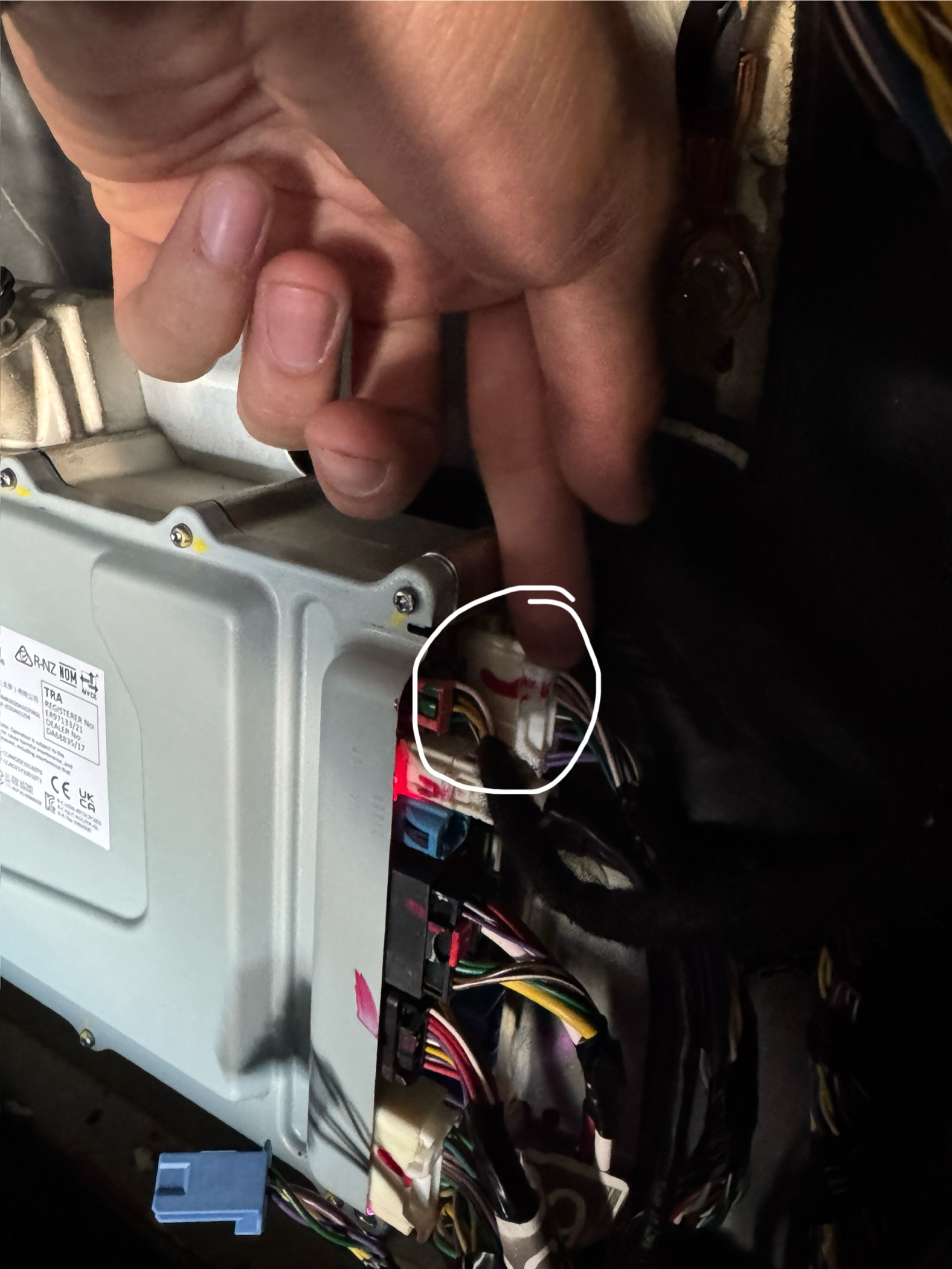
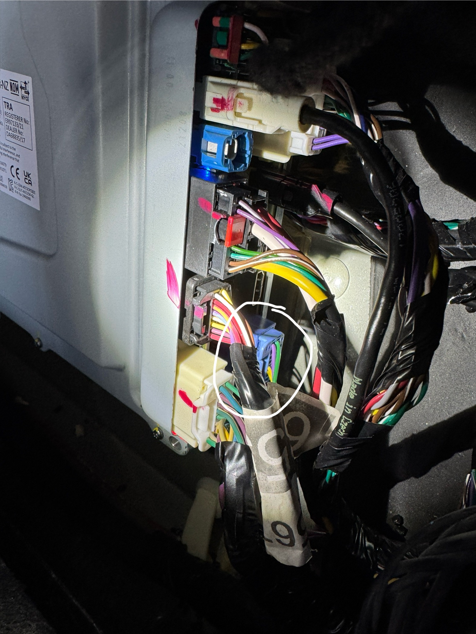
The CAN bus containing all of the information required is the chassis CAN bus on
pins 13 and 14 of the diagnostic CAN port
- Shoutout to this Reddit post for inspiring most of these methods, albeit my execution being much more primitive
- Also huge shoutout to this online post that contains a bunch of links and information on how to decode the CAN bus, known codes, etc.
- Use the logic analyzer (w/ CAN bus decoding) to get "baseline" CAN bus messages, and save messages to a CSV file
- Use logic analyzer again, but while recording data, perform action (open door, flash headlights, etc.) and save the messages to a CSV file
- Use a Python script to parse the messages from both CSV files (each row represents one section of a message, so to recreate a message, several rows need to be parsed)
- Filter out any identifiers from the second batch of messages that are also present in the baseline
messages
- Other filtering methods can be used as well, this one only works if the identifier corresponding with the action is not sent repeatedly (such as status updates)
- Print the remaining messages, removing any duplicate messages
| Description | ID | Data |
|---|---|---|
| Main screen on (just kidding maybe not?) | 551 |
0 31 1 1 0 1 0 1 |
| Right side windows | 518 |
0x3F5- Light status (ambient lighting, turn signals, headlights, etc.)- Second data byte is display brightness
- The ambient lighting brightness is linked to the display brightness
- If the ambient lighting is off, then this byte is equal to
0x00 - Note: The code currently doesn't adjust the brightness of the lights based off of this value, it just checks whether it equals zero
- Turn Signals (didn't end up using)
- First data byte
- Left TS Off:
0b0000 0001 - Left TS On:
0b0000 0010 - Right TS Off:
0b0000 0100 - Right TS On:
0b0000 1000 - Hazard Off:
0b0001 0101 - Hazard On:
0b0001 1010 - If no turn signal cycle is ongoing, then byte equals
0x00
- Second data byte is display brightness
0x3B3- UI Vehicle Status- Third data byte contains data regarding the display
- Bit number 2 (isolated using
0x04bit mask) is set if the display is in what I call "normal" mode, which is basically the normal UI when the car is on. Otherwise, if the bit is not set, the display could be off, on the sentry mode screen, the charging screen, etc.- This bit decides whether to play the start-up animation for the lights
espressif/led_strip library was used. As currently configured,
this library uses the Remote Control Transceiver (RMT) peripheral on the ESP32 to send the
signals on the data line. The RMT peripheral was originally intended for infrared transmissions, but it is
leveraged by the led_strip library to send the timing-critical pulses required to communicate
with the WS2815 LEDs.
The documentation for the LED strip library recommends using a chip with DMA
(direct memory access) in order to prevent context switches from interfering with the timing of the
signals.
The ESP-WROOM chip I used does not have DMA functionality, but I did not run into any issues since the
LED
strips used are pretty short.
                // required imports go here

                // LED strip common configuration led_strip_config_t strip_config =
                {
                    .strip_gpio_num = BLINK_GPIO,  // The GPIO that connected to the LED strip's data line
                    .max_leds = 110,                 // The number of LEDs in the strip,
                    .led_model = LED_MODEL_WS2812, // LED strip model, it determines the bit timing
                    .color_component_format = LED_STRIP_COLOR_COMPONENT_FMT_GRB, // The color component format is G-R-B
                    .flags = {
                        .invert_out = false, // don't invert the output signal
                    }
                };

                // RMT backend specific configuration led_strip_rmt_config_t rmt_config =
                {
                    .clk_src = RMT_CLK_SRC_DEFAULT,    // different clock source can lead to different power consumption
                    .resolution_hz = 10 * 1000 * 1000, // RMT counter clock frequency: 10MHz
                    .mem_block_symbols = 64,           // the memory size of each RMT channel, in words (4 bytes)
                    .flags = {
                        .with_dma = false, // DMA feature is available on chips like ESP32-S3/P4
                    }
                };

                void app_main(void)
                {

                    /// Create the LED strip object led_strip_handle_t led_strip;
                    ESP_ERROR_CHECK(led_strip_new_rmt_device(&strip_config, &rmt_config, &led_strip));
                    led_strip_clear(led_strip);

                    while (1)
                    {
                        uint8_t red = 255;
                        uint8_t green = 0;
                        uint8_t blue = 0;

                        for (int i = 0 ; i < strip_config.max_leds ; i++) {
                            led_strip_set_pixel(led_strip, i, red, green, blue);

                            if (red > 0 && blue == 0) {
                                red -= 15;
                                green += 15;
                            } else if (green > 0) {
                                green -= 15;
                                blue += 15;
                            } else if (blue > 0) {
                                blue -= 15;
                                red += 15;
                            }
                        }

                        led_strip_refresh(led_strip);
                        vTaskDelay(1000 / portTICK_PERIOD_MS);
                        led_strip_clear(led_strip);
                        vTaskDelay(1000 / portTICK_PERIOD_MS);
                    }
                }
Note: The TWAI interface on the ESP32 still requires a CAN bus transceiver chip to
convert the differential signal to a logic level signal that can be read by the ESP32 (I used the
SN65HVD230)
                // required imports static const char* TAG = "can_sniffer";

                // TWAI configuration twai_general_config_t g_config = TWAI_GENERAL_CONFIG_DEFAULT(GPIO_NUM_21, GPIO_NUM_22, TWAI_MODE_NORMAL);
                twai_timing_config_t t_config = TWAI_TIMING_CONFIG_500KBITS();
                twai_filter_config_t f_config;

                uint8_t data[16];

                void app_main(void)
                {
                // Configure TWAI acceptance mask
                // As configured, only accepts messages from 0x7F5.
                // Check ESP32 TWAI driver documentation for more information on how to set these values
                f_config.acceptance_mask = 0x1FFFFF;
                f_config.acceptance_code = 0x7EA00000;
                f_config.single_filter = true;

                // Install TWAI driver if (twai_driver_install(&g_config, &t_config, &f_config) == ESP_OK) {
                    ESP_LOGI(TAG, "Driver installed");
                } else {
                    ESP_LOGI(TAG, "Failed to install driver");
                    return;
                }

                // Start TWAI driver if (twai_start() == ESP_OK) {
                    ESP_LOGI(TAG, "Driver started");
                } else {
                    ESP_LOGI(TAG, "Failed to start driver");
                    return;
                }

                while (1)
                {
                    // Wait for the message to be received twai_message_t message;
                    esp_err_t receive_status = twai_receive(&message, pdMS_TO_TICKS(1000));

                    if (receive_status == ESP_ERR_TIMEOUT) {
                    ESP_LOGI(TAG, "Timed out waiting for message");
                    continue;
                    } else if (receive_status != ESP_OK) {
                    ESP_LOGE(TAG, "Error receiving message");
                    return;
                    }

                    // Compare new message data with saved message data if (memcmp(data, message.data, message.data_length_code) != 0) {
                    // Process received message if (message.extd) {
                        ESP_LOGI(TAG, "Message is in Extended Format");
                    } else {
                        ESP_LOGI(TAG, "Message is in Standard Format");
                    }

                    ESP_LOGI(TAG, "ID is 0x%03X", (unsigned int) message.identifier);
                    if (!(message.rtr)) {
                        // Copy new message data memcpy(data, message.data, message.data_length_code);

                        // Format data into single string char data_string[128];
                        for (int i = 0 ; i < message.data_length_code ; i++) {
                        char buffer[16];
                        sprintf(buffer, "%02X ", data[i]);
                        strcat(data_string, buffer);
                        }
                        ESP_LOGI(TAG, "Data: %s", data_string);

                        // Clear data string for next iteration memset(data_string, 0, 128);
                    }

                    }

                }
                }
more commands to be added here
ambient_light_t struct, containing members for the
led_strip library configuration. When an ambient_light_t is initialized using the
init_ambient_light method, a new task is started dedicated to controlling that light, and a
FreeRTOS queue is created for commands to be sent to the LED strip. The process for controlling an
ambient_light_t is as follows:
- Add a
command_t*to the command queue- The command contains information on what the command is, along with any other data required the
command (
rgb_tforCOMMAND_FADE_TO, etc.)
- The command contains information on what the command is, along with any other data required the
command (
It is the responsibility of the one adding the command to the queue to properly
allocate memory for the
command_t*. Once the command has been executed, the light
controller will deallocate the memory used by the command pointer and will set the pointer to
NULL
as well. This also means that each command must be allocated memory before being sent to the
light controller queue, and commands cannot be reused.
led_strip functions to control the LED strip specified in the
ambient_light_t struct. narray ofambient_light_thandles is shared inmain_common.hso that any class is able to send commands to the LED strips, assuming thatambient_light_thas been initialized correctly. This is utilized for the startup animation where the dashboard LEDs, after completion of their animation, start the sequential animation for the door LEDs, among other things. For simplicity, a commonrgb_tis also shared so that the HTTP server only has to update one color to ensure all lights are the same color.
- If the display goes from any non-normal state (off, sentry, etc.) to normal UI, then turn on the lights
with the startup sequential animation
- This prevents the full startup animation from starting if the lights are turned on/off while the car is "operational" (ex. while driving) since the animation can be a bit distracting
- If the ambient lighting brightness goes from non-zero to zero while the display is in normal UI mode, then fade the lights off
- Likewise, if the ambient lighting brightness goes from zero to non-zero while the display is in normal
UI mode, then fade the lights to the currently set color
- This allows for the lights to be controlled using the "Ambient Lights" button in the "Lights" vehicle control menu just like the OEM ones (ex. one driver profile can have the ambient lights turned off, while another can have them on)
curl
to send a new binary image for the ESP32 to a specific endpoint while connected to the AP hosted by the ESP.
The ESP32 partition table needs to be configured to support OTA updates by having
multiple
ota partitions. EspressIf provides a default OTA partition table that I
used
- When a
.binfile is uploaded to/otaendpoint, thehttp_servertask starts the OTA update process - A handle to the non-active
otapartition is retrieved usingesp_ota_get_next_update_partition - The image header is first downloaded from the client and checked. If there are no errors, then
esp_ota_beginis called to setup writing to theotapartition that will store the new partition - While the HTTP server is receiving data,
esp_ota_writeis called to write the binary image being sent into theotapartition chunk by chunk until all data has been received - A response is sent to the client stating that the image has been received and that the ESP is now being restarted
- The boot partition is swapped to the
otapartition containing the new binary image - The ESP is restarted and will boot using the new binary image
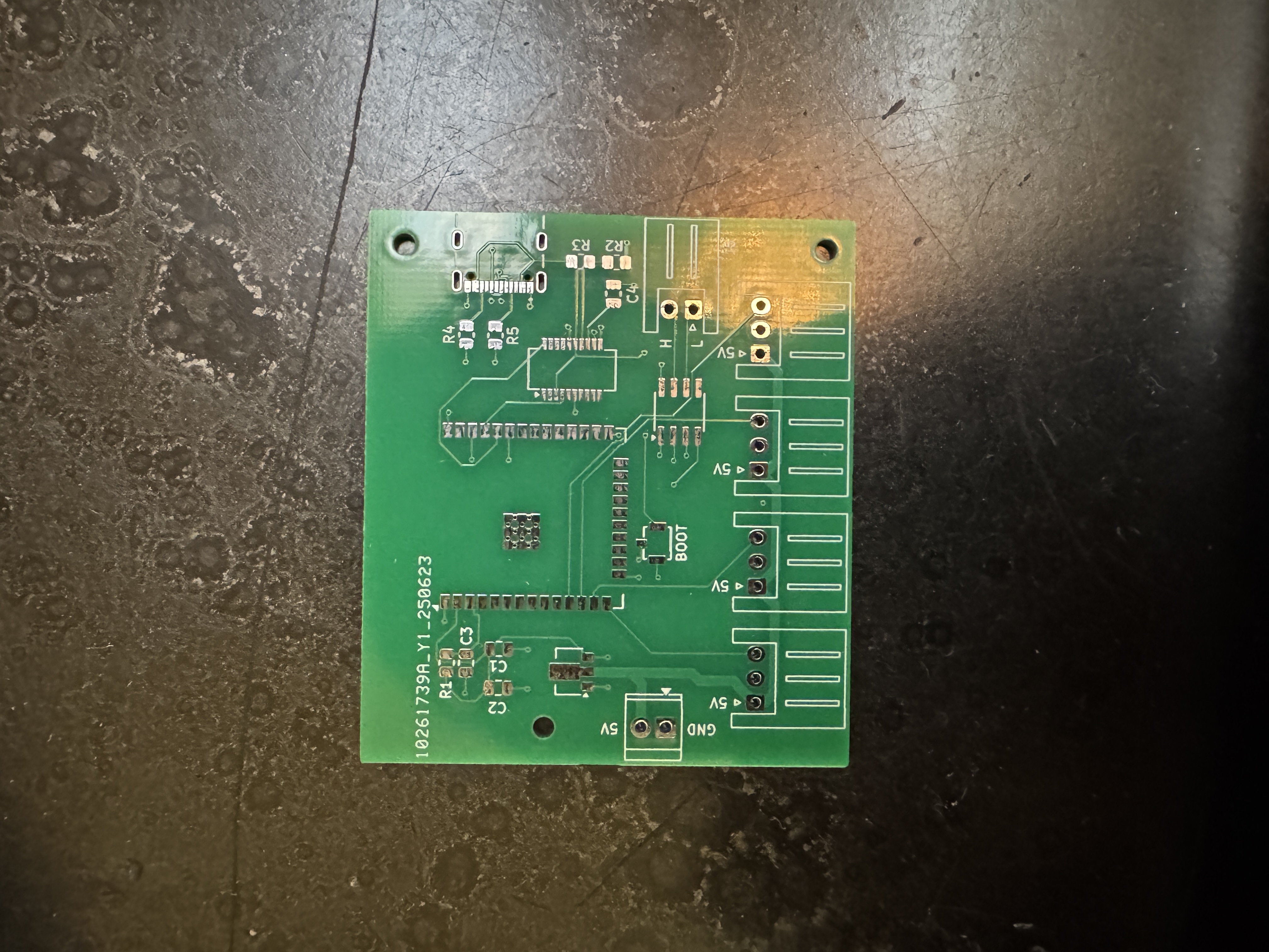
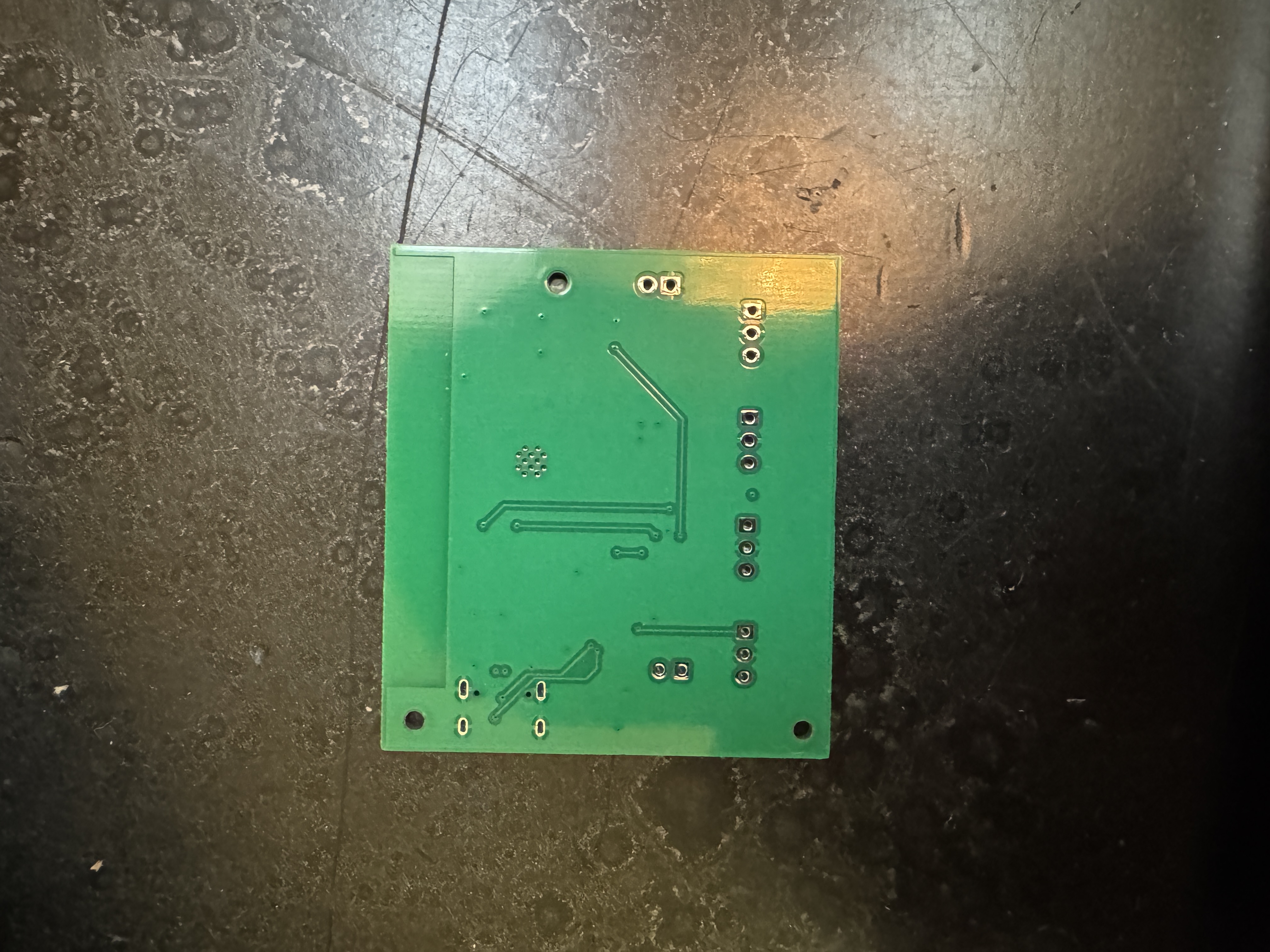
Seeing as this was my first time putting together a PCB, there were some issues.
RC Delay Circuit Issue
- I don't know why this was happening, and it is recommended by Espressif to have this circuit to add ~10ms delay to the EN pin, but it works fine without it so ¯\_(ツ)_/¯
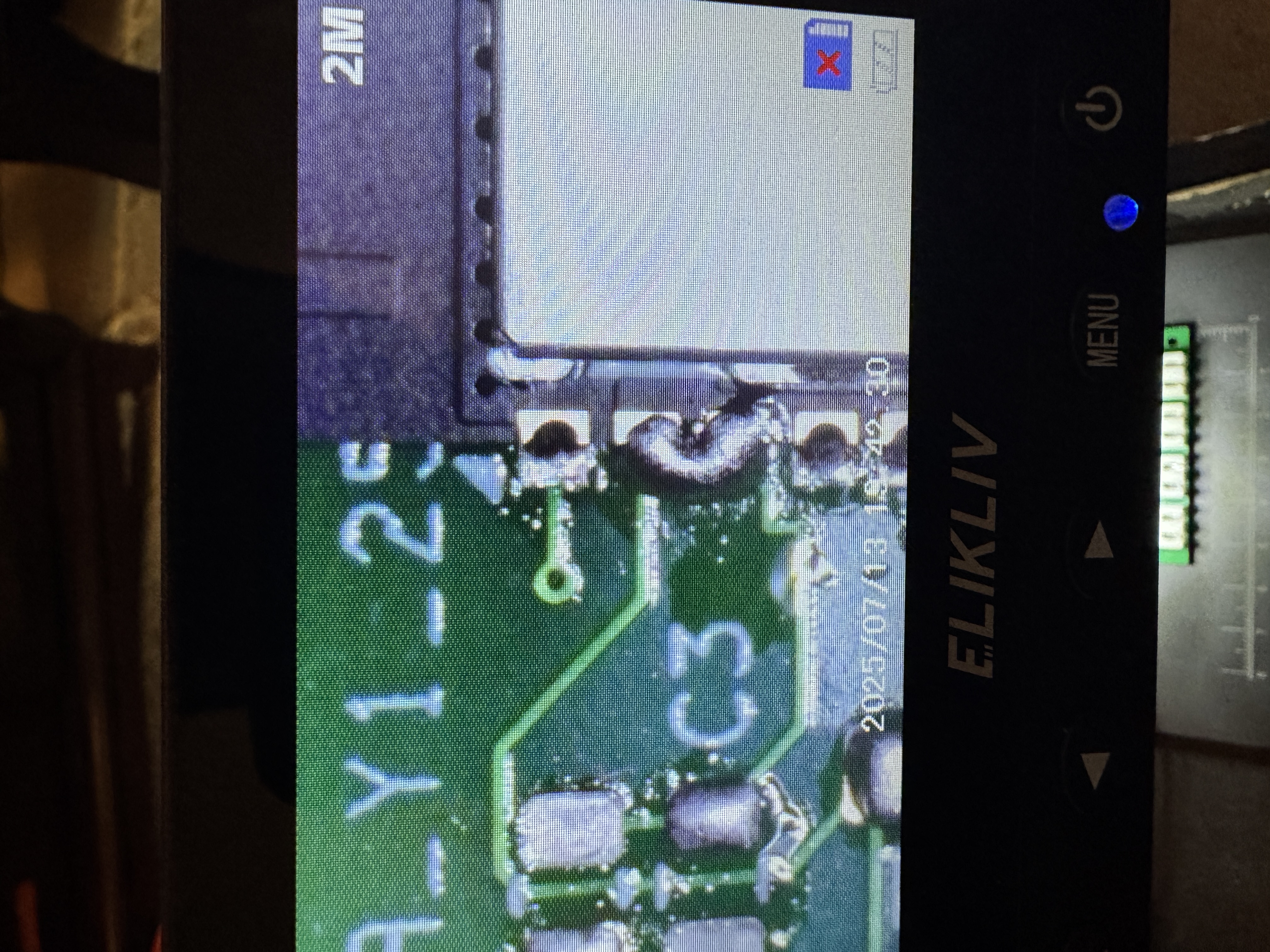
Not Enough Heat
When I was soldering the ESP32, I didn't heat up the chip enough, so there ended up being some gaps on the pads which caused one of the lights to not work.
- A reset button that pulls the EN pin on the ESP32 low so that the USB cable or power source doesn't have to be disconnected every time
- Utilizing the DTR and RTS pins on the FT231XS USB-UART chip so that the ESP can be automatically restarted and put into bootloader mode when uploading firmware
👀
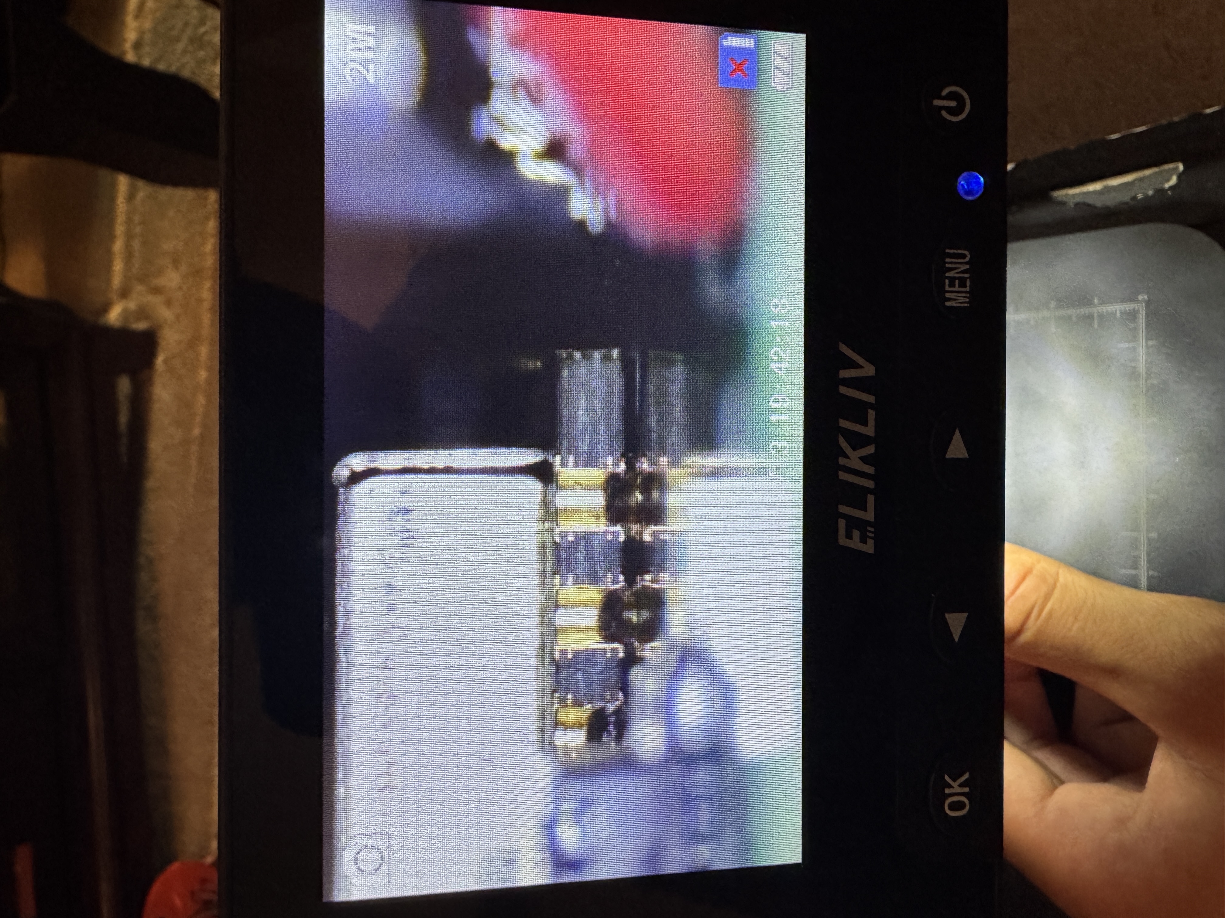
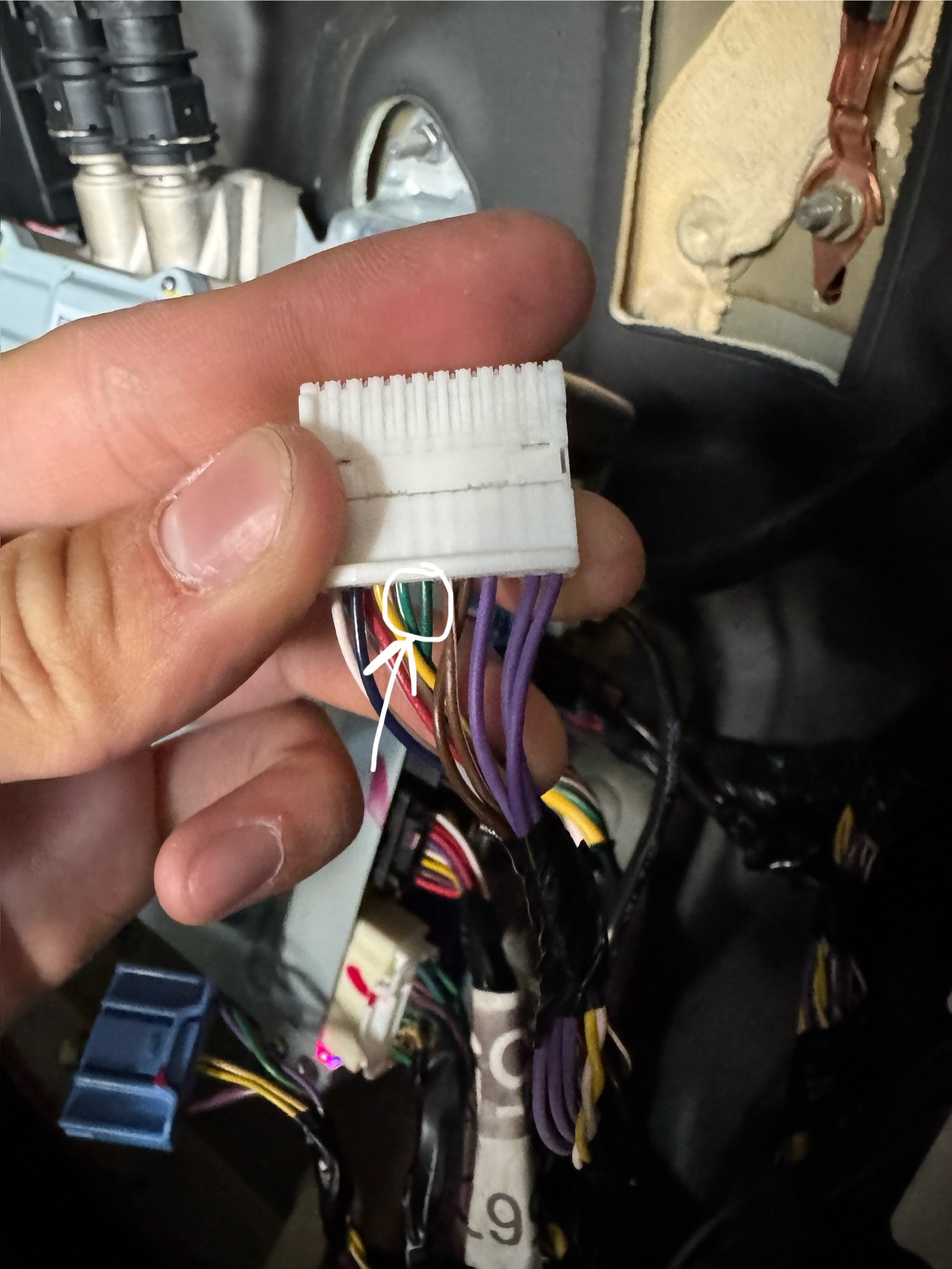
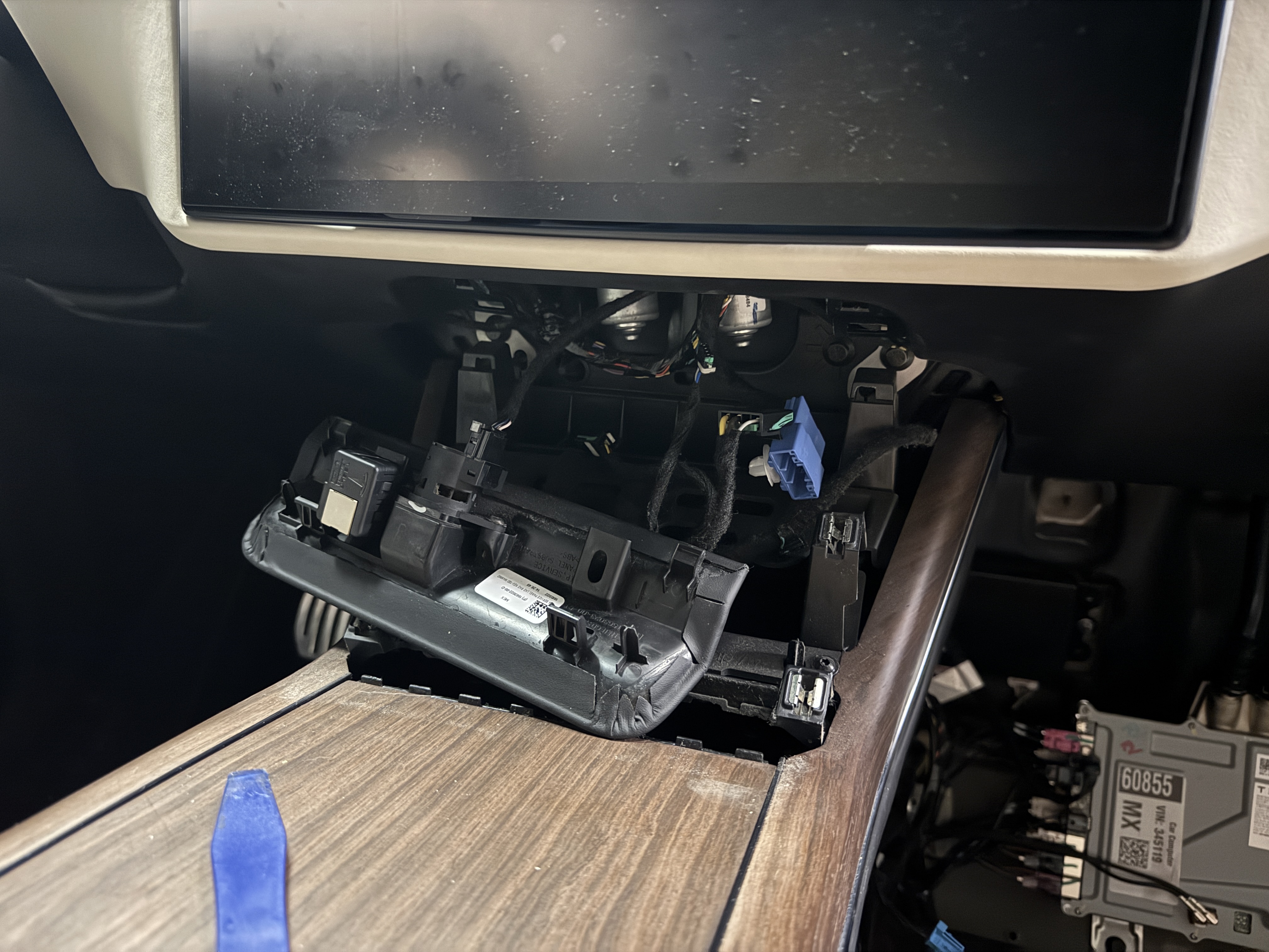
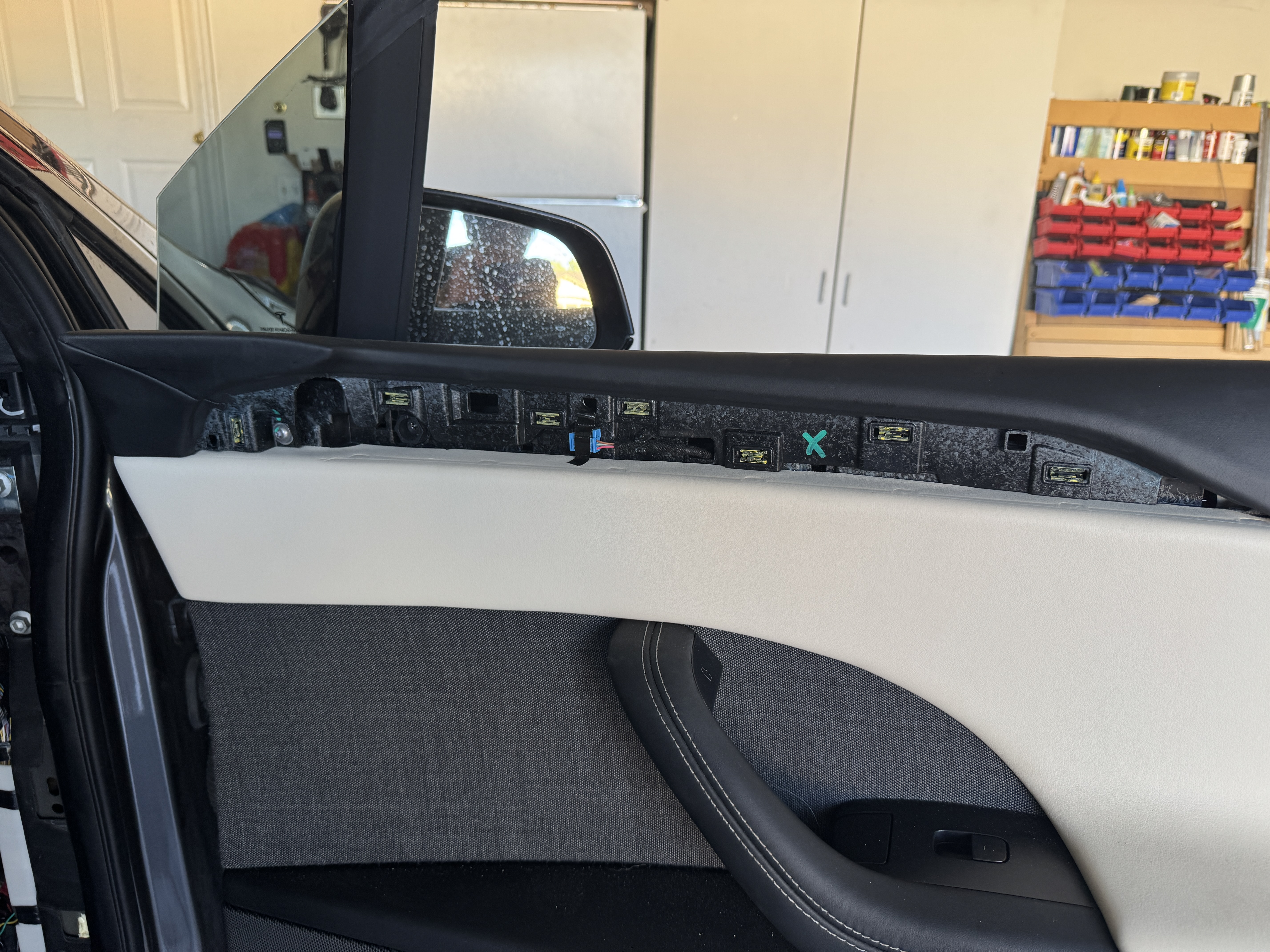
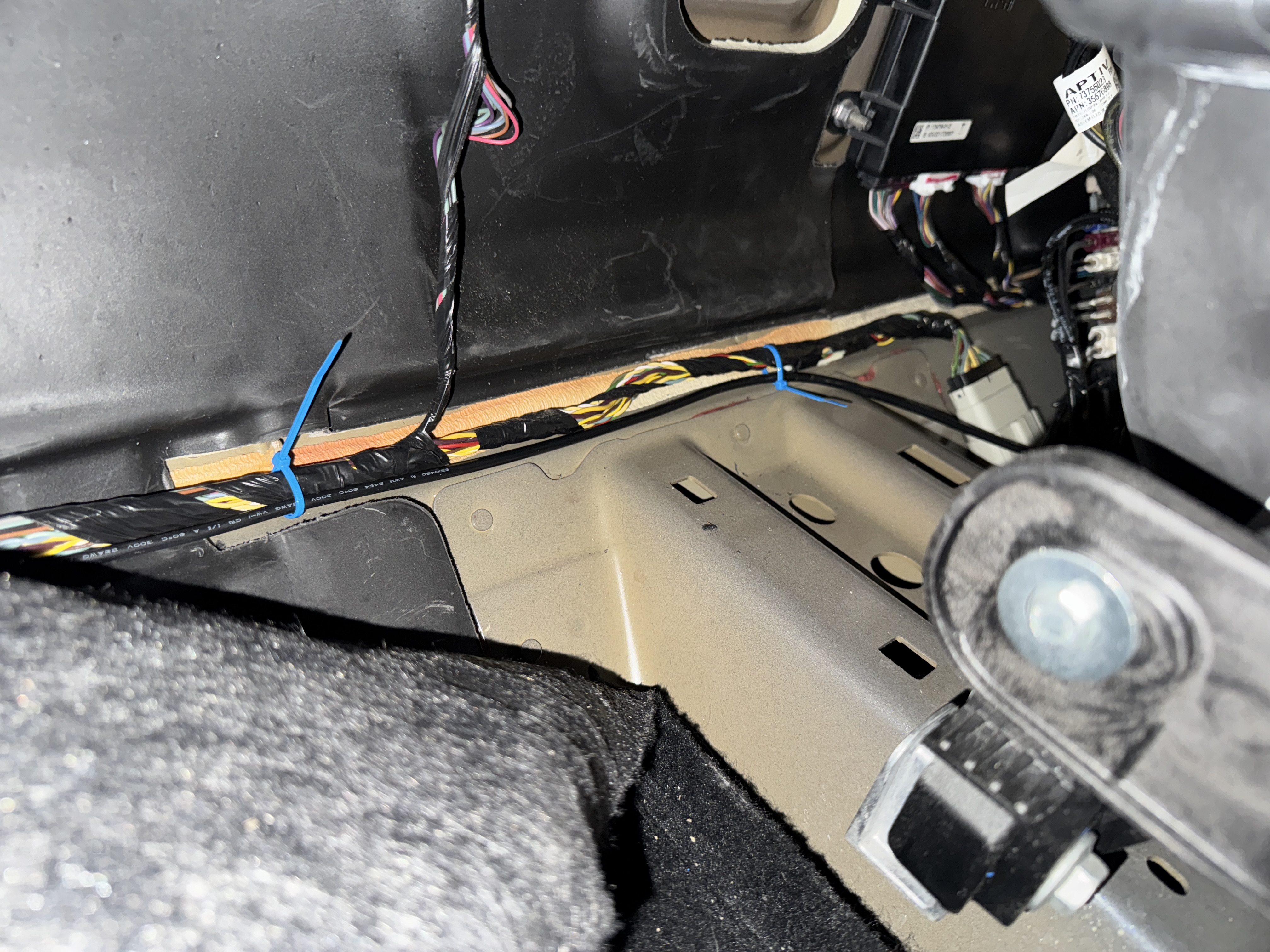
There are extra 3-pin connectors that are not plugged into anything in both door
panels, and also in the center console and dashboard. I believe these are there from earlier attempts at
adding ambient lighting by Tesla, and I spent a couple of hours seeing if I could hijack the wires for
communication with my light controller, but in the end I decided it wasn't worth risking damage to the ECUs
or other components.
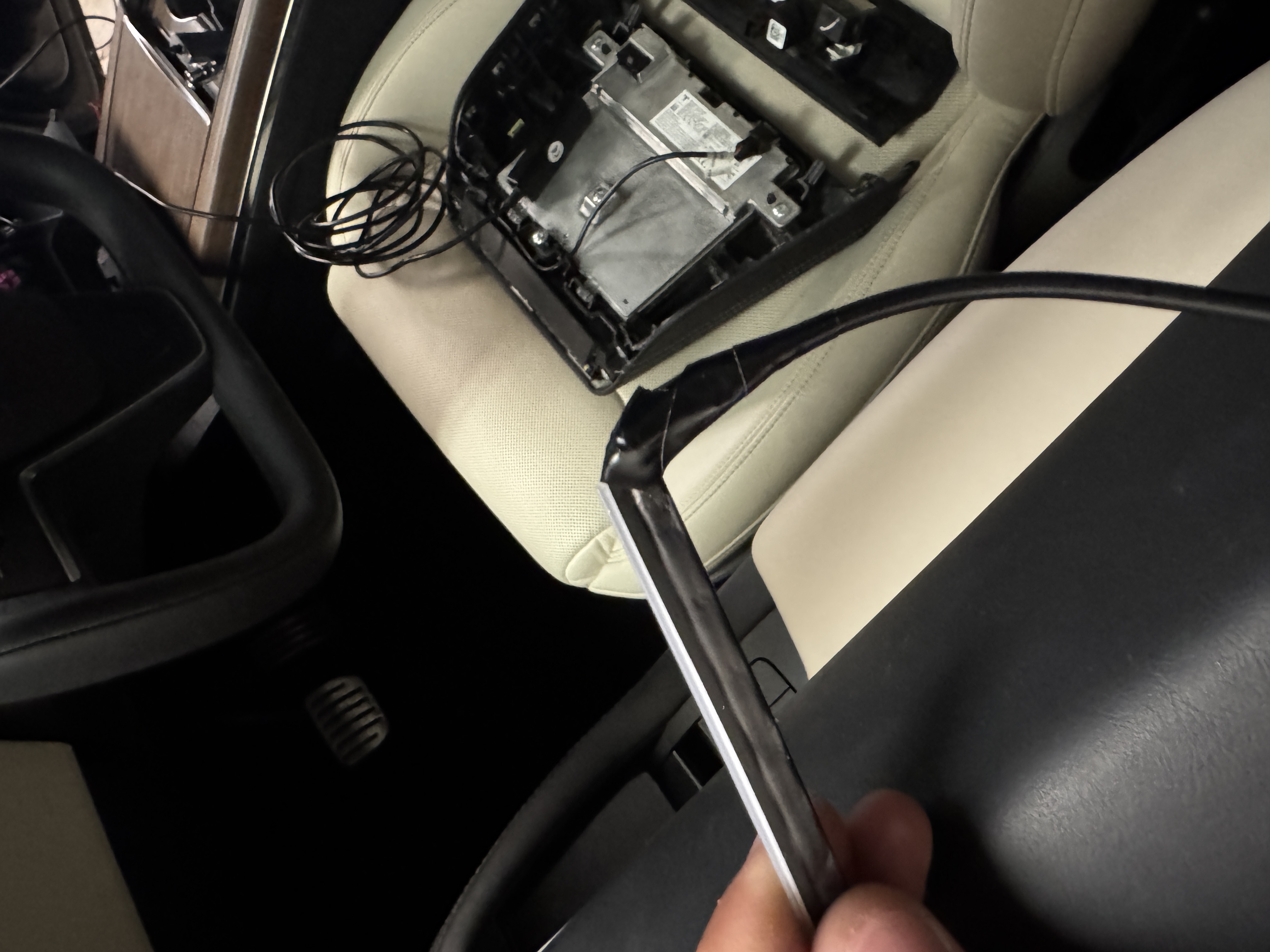
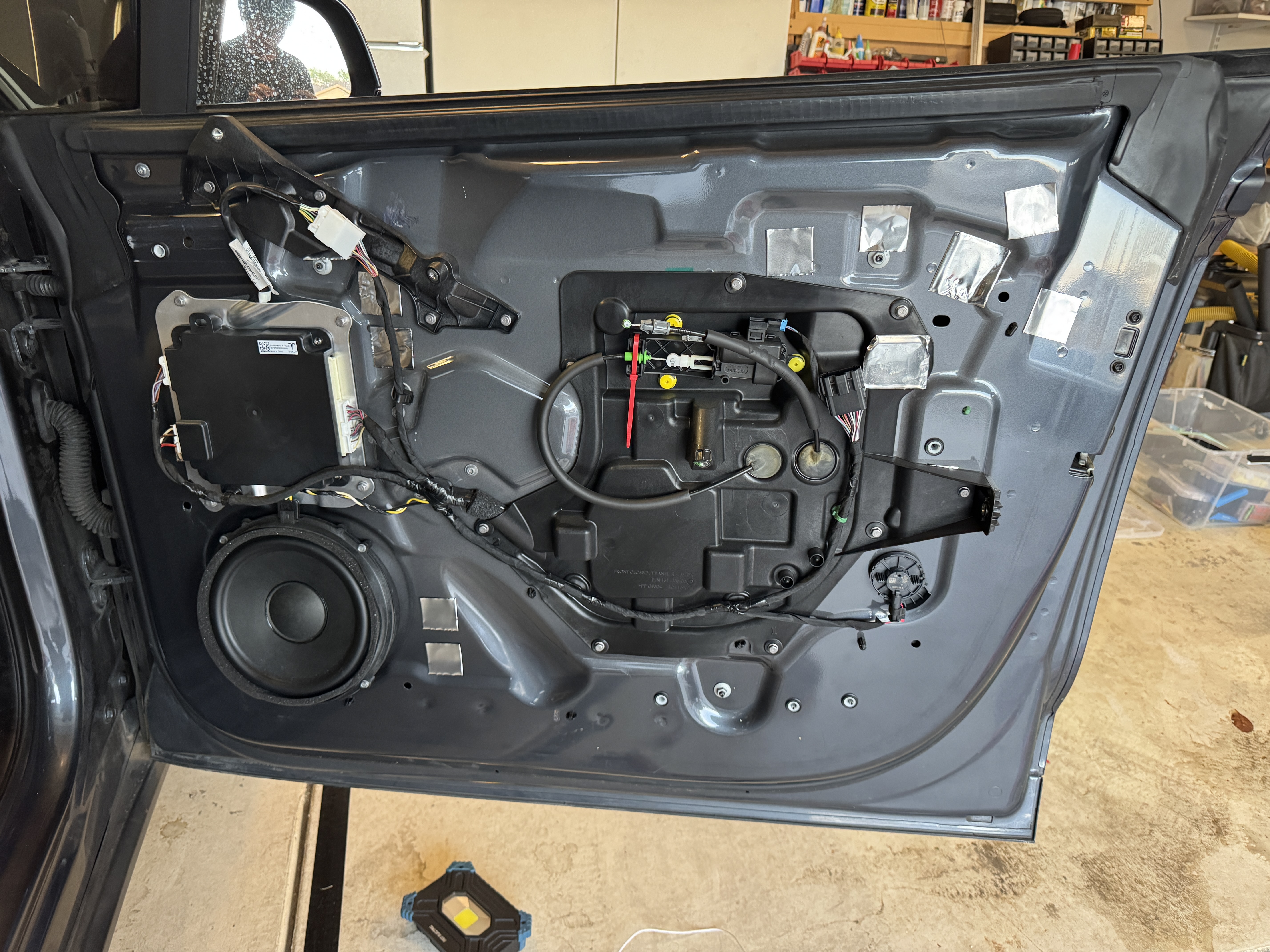
Tip: The Tesla service manual states to roll the window down when removing the door
panel, which I did do. However, I then temporarily plugged the door panel back in to roll the window up
so
that I had more room inside of the door. Just make sure to leave a window open on the other side,
especially
if you disconnect LV power since that could possibly lead to you being locked out of the car.

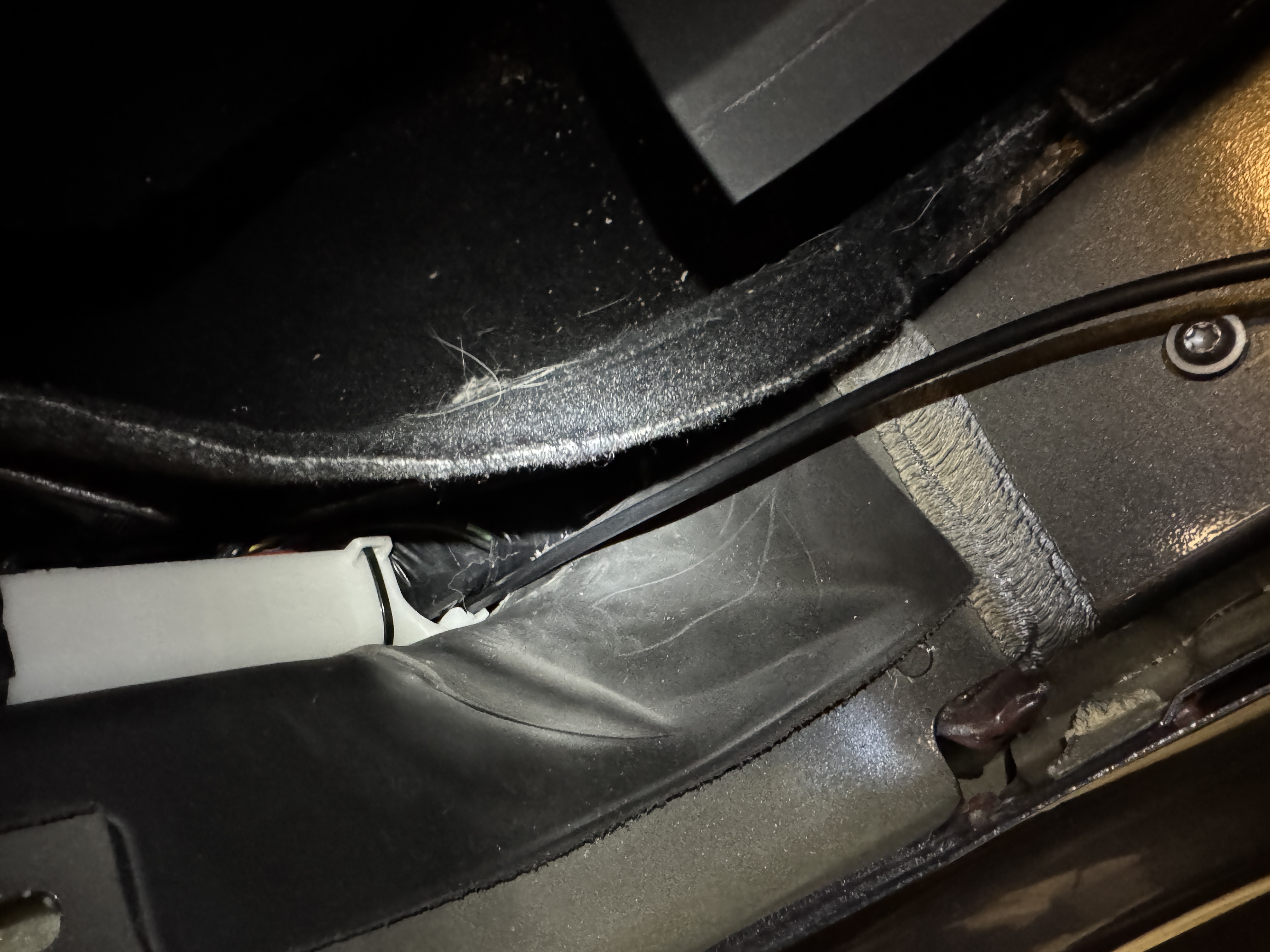
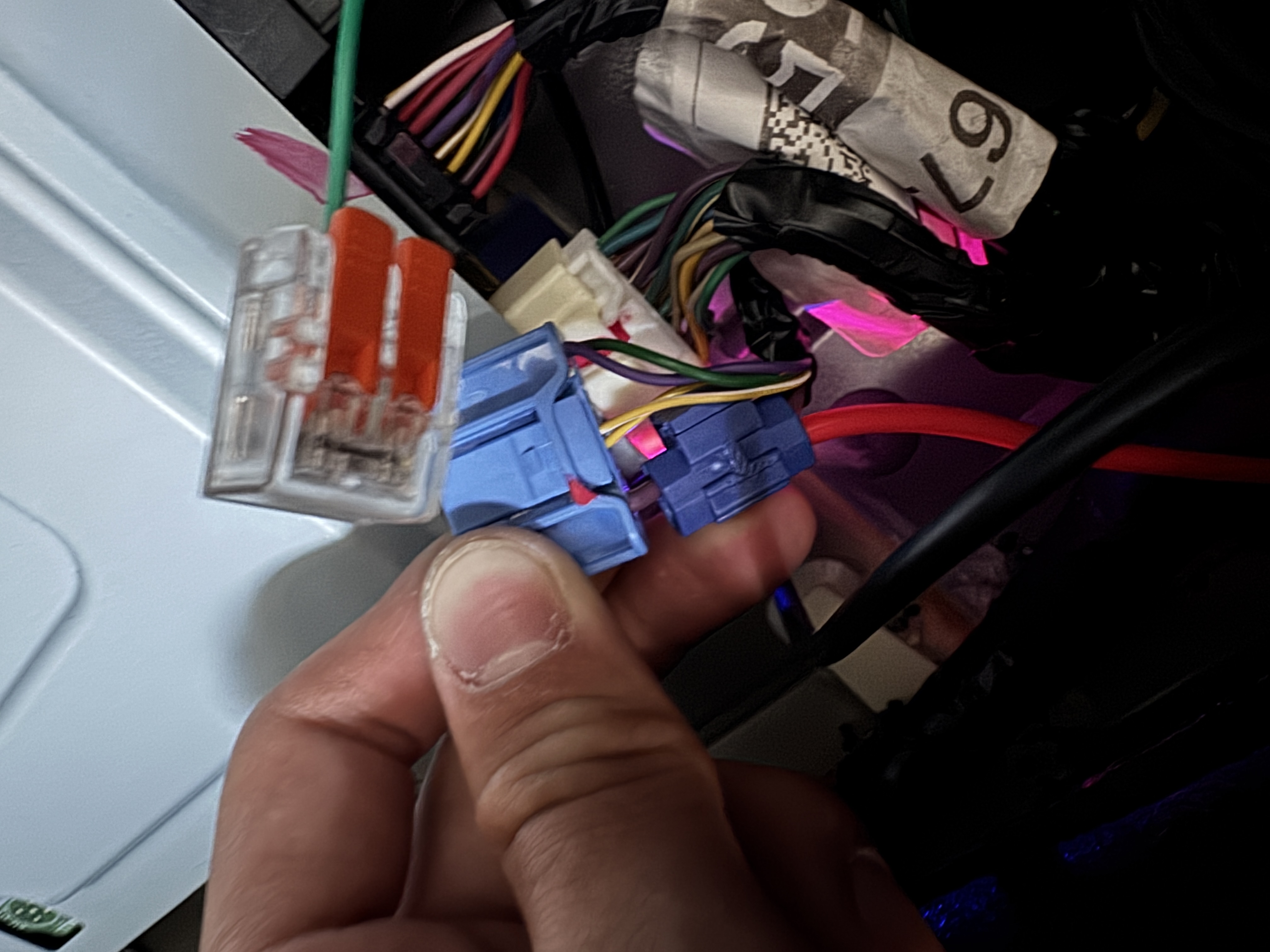
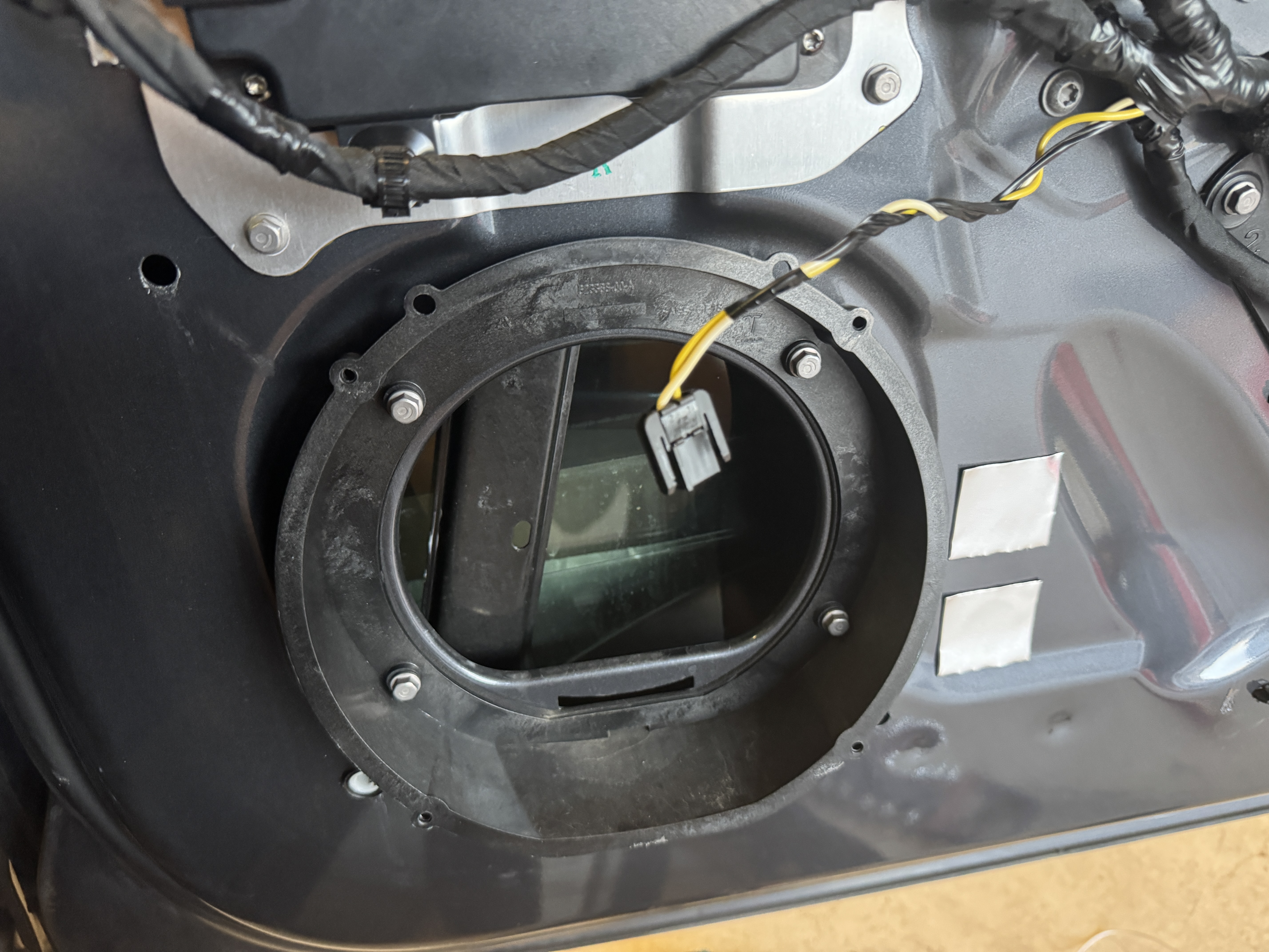
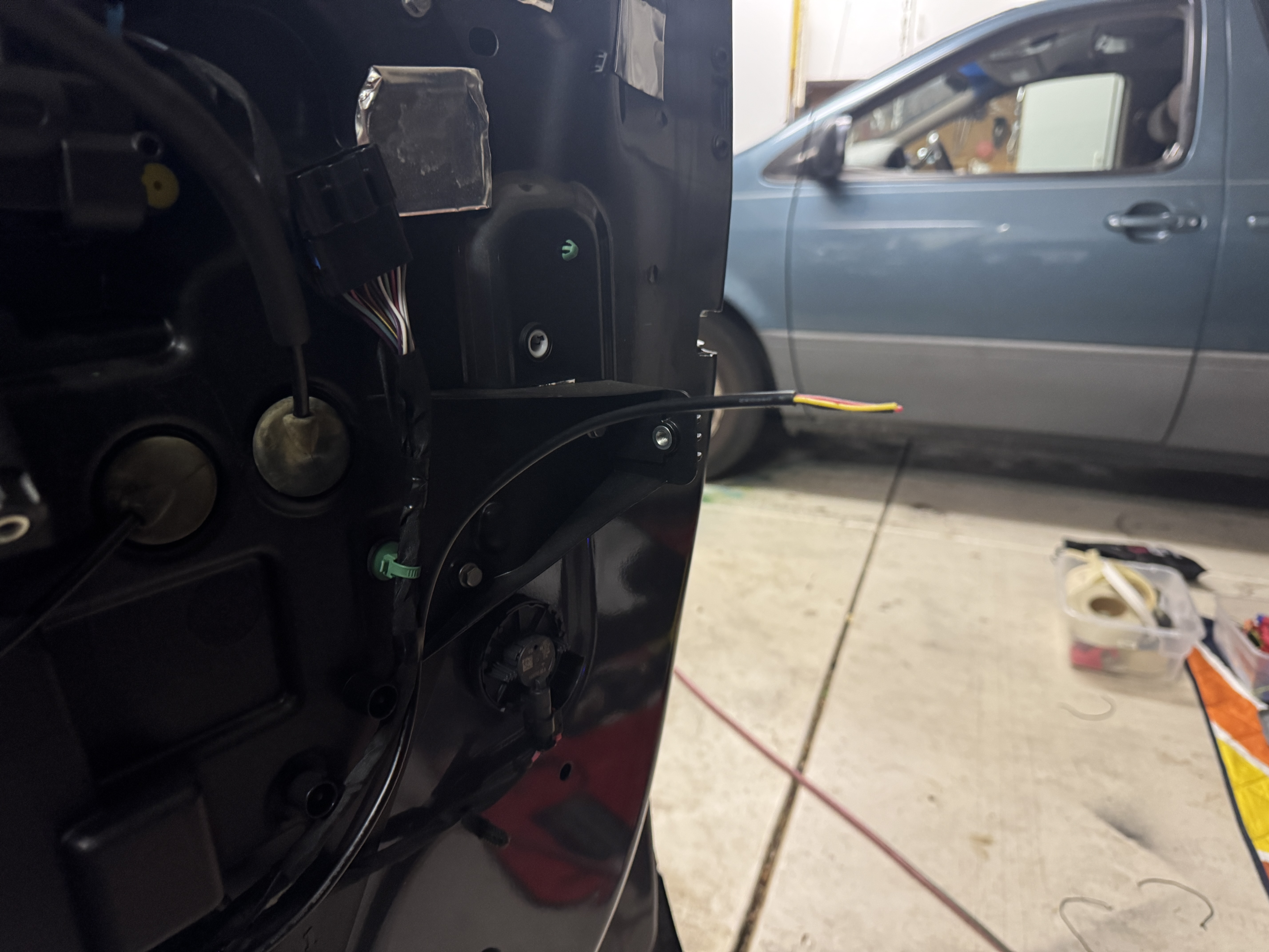
I used 3 pin JST-XH connectors between the door panel and the door so that, in the
future, the door panel can be removed fully just by disconnecting the existing connectors along with the
3
pin connector for the ambient lighting.
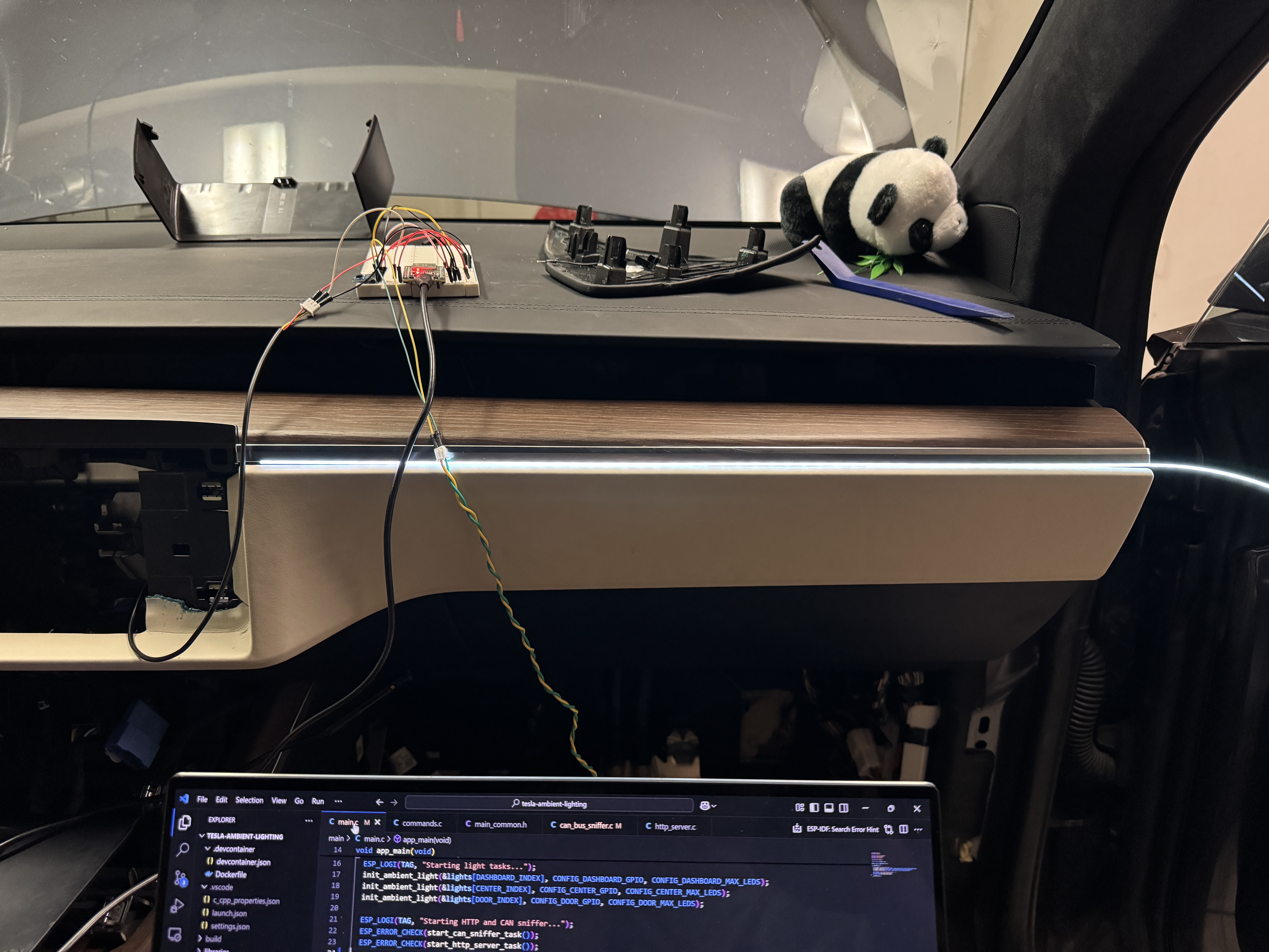
0x646464 (around half brightness pure white). This
ended up being a little too bright for my taste, and I have since moved to 0x503C14 for a dim
warm white color that is much easier on the eyes.